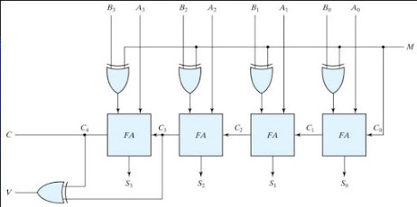
Simulate Overflow detection Using Verilog
Overflow Occurs with respect to addition when 2 N-bit 2’s Compliment Numbers are added and the answer is too large to fit into that N-bit Group.A computer has N-Bit Fixed registers. Addition of two N-Bit Number will result in max N+1 Bit number. That Extra Bit is stored in carry Flag. But Carry does not always indicate overflow.
Module:
This File Should be placed in overflowdetection.v
input x;
input y;
input cin;
output sum;
output cout;
output flow;
assign sum=((x^y)^cin);
assign cout=(((x^y)&cin)^(x&y)); assign flow= (cin^cout);
endmodule
Test Bench:
This File Should be placed in overflowdetection_tb.v
`timescale 1ns/1ns
module overflowdetection_tb;
reg x;
reg y;
reg cin;
wire sum;
wire cout;
wire flow;
overflowdetection uut(x,y,cin,sum,cout,flow);
initial begin
$dumpfile("overflowdetection_tb.vcd");
$dumpvars(0,overflowdetection_tb);
x=0; y=0; cin=0;
#5 x=0; y=0; cin=1;
#5 x=0; y=1; cin=0;
#5 x=0; y=1; cin=1;
#5 x=1; y=0; cin=0;
#5 x=1; y=0; cin=1;
#5 x=1; y=1; cin=0;
#5 x=1; y=1; cin=1;
end
initial begin:
$monitor("t=%3d,\t x=%d,\t y=%d,\t sum=%d,\t
cout=%d,\t flow=%d\n",x,y,cin,sum,cout,flow);
end
endmodule
RESULT:
 If you have problem on installing verilog on windows or linux then click here


